My first computer was a ZX81, and as child I always wanted to make my own computer. However I always found writing software easier, and moved away from electronics to software. The Arduino rekindled some of that delight in physically making things,
so I started to wonder if an Arduino could help me understand how old 8-bit processors work, and kickstart the process of building one.
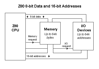
I bought two Z80s from RS Components, and after realising I was going to need a lot more digital pins than the Uno provides, an Arduino Mega. The video below shows my set-up running in test mode, which I reset at the beginning. The LEDs in the bottom right are power (green), clock (yellow) and reset (red). The reset blinks 3 times, to clear the Z80 program counter and probably it's registers. I read somewhere that 3 times was better than just once, but I'll play around with that to see if it's true.
The strip of LEDs at the top left are the low bytes of the address bus. The yellow is the 1's and the red the 128. Oddly once I hit 128 in the PC unexpected things start to happen. The LEDs at the top right are memory request (blue), read data (red) and write data (yellow).
When the processor is reset, it's also fed 0's on all of its data lines. This means that when the program counter requests each instruction, it gets a NOP (no operation). This causes the program counter to increase by one, hence the address bus counts up in binary. Right now all the Arduino Mega is doing is monitoring the address lines and outputting the result to the serial monitor. This works, and proves at least that the Arduino is capable of limited support of the Z80, as well as making me more happy that I probably should be. One thing to love about the Z80 is that the clock signal can be manual, you can literally step through the instruction processing.
I've uploaded the very basic code to GitHub here.
The next step is to make the software recognise the memory request & read data signals to provide instructions, effectively working as a ROM. The after support RAM and IO. I plan to use a small Arduino controlled OLED display to act as an output for now. No idea about input though!

No comments:
Post a Comment